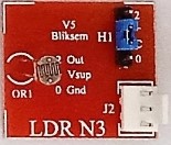
Input Modules

Switches N2:

S1 Tact Switch, S2 reed switch and S3 Leaf switch. Input supply at J1 and switched output

LDR N3:

Light Dependant Resistor (LDR) has two terminals. One terminal of LDR is output (2). With jumper cap (blue) on header H1, it is possible to set the other terminal of the LDR to be ground (C,0) or +supply (C, +). Its resistance in dark is > 100K Ohms, and few Ohms in bright light.

Proximity Detector N5:

D1 is Infrared transmitter (IRT) and D2 is infrared receiver (IRR). It is used in applications to detect objects in its close proximity. The heat rays emitted by IRT will be received by IRR by object and outputs voltage at pin 2 in J1

Tilt Switch N8:

S1 is tilt Switch, Input supply at J1 at pin 1 . One terminal of switch is available at pin 2 of J1 and other terminal can be selected as +V or Ground by Jumper cap (orange)setting at TP

Level Probe N9:

Due to partial conductivity of water, When dipped in water (or moist soil), as the water level reaches points 2,3,4, supply voltage at pin1 of J1 will be available in pins 2 to 4.

Tact Switch N10:

S1 is temporary switch, when pressed connects output pin 2 of J1 to supply or ground as per Jumper cap settings. The capacitor C1 eliminates switch bouncing.

Thermistor probe N4:

When heated, the resistance reduces from very high value (100k ohms) to very low value (few Ohms)

Hall sensor N9:

J3 is Supply input. Q1 is linear magnetic field sensor and Q2 is nonlinear (Switching) sensor, J1 outputs voltage proportional to magnetic strength from Q1 and J2 outputs switched voltage from Q2, both in the presence of a magnet in their proimity

Auxiliary Modules

USB A1:

This USB module contains normal USB female (U21), USB C (U22) and micro-USB (U23). This module is used only for supply connection between power sources such as laptop, mobile phones, power bank etc and any USB equipment.

Time Delay A2:

Capacitor at C21 and resistor at R21 set discharging time. C21 and R23 set charging time. J1 is input, J2 and J3 are output. When Q21 is on, due to input positive pulse, the input supply at J1 is available at J2 and J3 until C21 discharges.

Var. Res A3:

By turning the spindle the resistance value can be varied from 100Ω to 100kΩ.

C Load Amp A4:

TO126 Darlington transistor (BD681) enables driving relays and motors. External load is connected between collector and supply at J2.

3 Way Con A5:

Power supply is connected to J3 and it is available on J1, J2 and J4. J3 has no signal connection. J1, J2 and J4 are interconnected for signal and supply.

Power – Fuse Switch A6:

The power supply input from a DC source of 6V, is applied at J1. Switched supply (Sw21) is available at J2 and J3. The fuse protects circuit. In J2 the middle pin and ground pin are connected whereas in J3 middle pin has no connection.

DVM A9:

Digital Voltmeter is used to measure voltages in a circuit. Use the probe, to connect the DVM input to measure voltages at test pins on any modules. The supply at J1 is available at J2.

Wire tester A11:

This module is used to validate the continuity of connecting cables. It can be used to test other cables fuse etc.

Main Modules

Musical Bell M2:

Electronic melody bell, Q11 in M2 has an embedded musical program that creates a musical signals, when supply is given to this module at J1 pin 2. Musical output available at J2 goes to amplifier before feeding speaker.

Op Amp M3:

Operational Amplifier (LM358) finds common use in many electronics applications. It has two inputs inverting – (J1) and non-inverting – (J2). It is used as a comparator and amplifier in the activities.

Motion Detector M4:

Motion detector is used to detect human/ animal movements up to arrange of 8 to 10 feet in front. Can be used to control lights, security alarm etc.

Three Trans. Amp M7:

3 NPN transistors (Q11-Q13) are used to amplify very small current given at the bases (from level detector) through J1.

NE555 M8:

NE 555 is a very versatile IC used in oscillators, timers, and bistable switch. Can be used to control servo motors using a potmeter at J4. All modes can be changed using header components.

7 seg Driver M12:

7 Segment display Driver is used to drive 7 segment LED displays used in many gadgets and machines to indicate numerals. They can be cascaded for multiple digit display.

Standard 2 input Logic gates such as AND, OR, NAND etc can be tested and used for projects by simply placing the logic IC in the Zip socket.

Output Modules

W.LED O1:

The white LED is activated (lit) when + V supply is at pin 1 and 0V at pin 2.

2 Col LEDs O2:

Colour LEDs can be used (at D31 and D32) with suitable current control resistors (R31,R32). LEDs and resistors can be easily changed to suit application.

Tri LED O3:

R, G, B colour LEDs are in a common anode transparent encapsulation. They can be activated individually or together.

UV-W. LED O4:

4 LEDs are used to give more light. LEDs can be changed between UV LEDs or White LEDs. Serial and parallel resistor combination can be tested.

7 segment Display O6:

Numerals 0 to 9 can be displayed in each such modules using the display driver module. The Headers H1 and H2 are to be interfaced with display driver module.

Buzzer O7:

The buzzer is a polar device with anode and cathode terminals. When Dc voltage is applied, it outputs shrill sound.

2P2W Relay O9:

Two-pole Two-way relay module helps to drive motor in either direction and, also helps to isolate relay driving supply and motor supply.

1P2W Relay O10:

The load can be connected to normally open or closed contact of the relay. The power supply can be isolated or not. Using a diode, load drive can be latched.

USB Motor with fan blades:

It is a simple DC motor with soft and safe fan blades. With micro USB or USBC connection. The load speaker needs to be connected to amplifier module A4.